
Videos
The
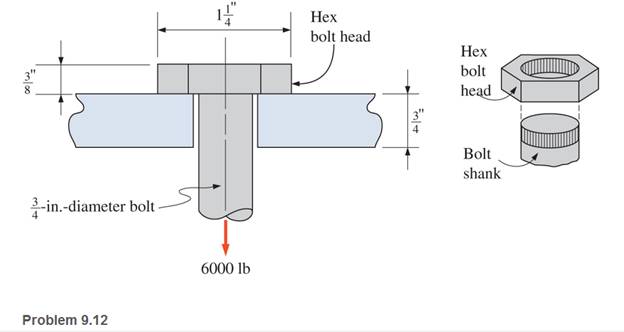
a. the tensile stress in the bolt
b. the shear stress in the head of the bolt

Learn your wayIncludes step-by-step video

Chapter 9 Solutions
Applied Statics and Strength of Materials (6th Edition)
Additional Engineering Textbook Solutions
INTERNATIONAL EDITION---Engineering Mechanics: Statics, 14th edition (SI unit)
Manufacturing Engineering & Technology
Automotive Technology: Principles, Diagnosis, And Service (6th Edition) (halderman Automotive Series)
Engineering Mechanics: Statics & Dynamics (14th Edition)
Automotive Technology: Principles, Diagnosis, and Service (5th Edition)
Applied Fluid Mechanics (7th Edition)


- Two steel rods are welded together (see figure): the seam is oriented at angle ? = 50°. The stresses on the rotated element are sx1=10 ksi, sy1= -12 ksi, and tx1y1= -5 ksi. Find the state of plane stress on the clement if it is rotated clockwise to align the x3 axis with the longitudinal axis of the rods.arrow_forwardThe vertical load P acting on the wheel of a traveling crane is 13,000 lb. What is the average shear stress in the 1.25 in. diameter axle?arrow_forwardA 20 in-diameter air compressor is operating with a maximum pressure of 24 psi. The bolts have a yield stress of 4350 psi. Which of the following is the stress area in sq. in. of the bolt? (Hint: Solve for the applied load first using the given pressure)arrow_forward
- Calculate the principal stresses at point A for the loading case.arrow_forward3. Calculate the bearing stress and shear stress between the pin and each bracket of a clevis joint. Assume pin diameter of 10 mm, 40 mm wide gap link, 12 mm thick bracket, and 3550N tensile load. Draw a free body diagram (geometry & forces) Identify stress plane Calculate stress and write it (with appropriate units) in the outlined boxarrow_forwardA 4 inches diameter journal bearing with 3 inches long has a load of 50 kN. Find the stress developed.arrow_forward
- For the stresses given with the cube below: 1. Compute the center, radius (R), principal normal stresses (0₁ and 03), max shear stress (Tmax) and draw the Mohr's Circle. 2. Compute the normal and shear stresses when the cube is rotated 20° clockwise from the horizontal plane and draw them on the cube. 3. The yield point stress (σyp) is 6 kPa. Determine if the material will fail under stresses shown using Tresca's Hexagon. вкра акра 6 экра 8 кра экра 4краarrow_forwardA 3/8-inch diameter bolt is subjected to a 2,085-lb tensile load. The bolt passes through a very thick plate to restrain it. Compute the tensile stress in the bolt. Your Answer:arrow_forward3. Calculate the contact stress between a 100-mm- diameter steel ball weighing 500 g sitting on a hardened steel surface plate.arrow_forward
- The stress in a wire of diameter 2 mm if a load of 100 gm is applied to a wire.arrow_forwardeach sold bar has a 36N/m weigh If the 1:In the following arrangement of structur allowable shear stress in pin C is 16 Mpa calculate the pin diameter at A. If the diameter of bar is (10 mm) what is the bearing stress on bar AB. 36N/M 2m im Im 2marrow_forwardSolve for the indentation diameter if the BHN of the material is 70 and a 500 kg of load is applied? Use indenter diameter 10mm.arrow_forward
 Mechanics of Materials (MindTap Course List)Mechanical EngineeringISBN:9781337093347Author:Barry J. Goodno, James M. GerePublisher:Cengage Learning