
Concept explainers
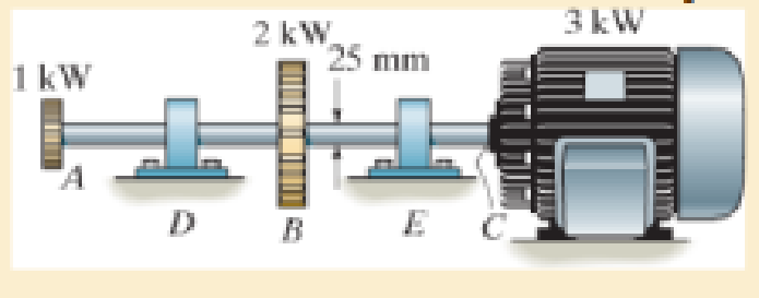
The solid steel shaft AC has a diameter of 25 mm and is supported by smooth bearings at D and E. It is coupled to a motor at C, which delivers 3 kW of power to the shaft while it is turning at 50 rev/s. If gears A and B remove 1 kW and 2 kW, respectively, determine the maximum shear stress in the shaft within regions AB and BC. The shaft is free to turn in its support bearings D and E.

Learn your wayIncludes step-by-step video

Chapter 5 Solutions
Mechanics of Materials (10th Edition)
Additional Engineering Textbook Solutions
Engineering Mechanics: Statics
Applied Statics and Strength of Materials (6th Edition)
INTERNATIONAL EDITION---Engineering Mechanics: Statics, 14th edition (SI unit)
Engineering Mechanics: Statics & Dynamics (14th Edition)
Thinking Like an Engineer: An Active Learning Approach (4th Edition)
Automotive Technology: Principles, Diagnosis, and Service (5th Edition)


- The steel shaft DF consists of three concentric tubes and is supported by smooth bearings at D and E. It is coupled to a motor at F, which delivers 15 kW of power to the shaft while it is running at 55 rev/ sec. The gears A, B, and C remove 4 kW, 5 kW, and 6 kW, respectively. The shaft is free to turn in its support bearings D and F. Determine the shearing stress developed in segments BC and CEarrow_forwardThe shaft has an outer diameter of 100 mm and an inner diameter of 80 mm. If it is subjected to the three torques, plot the shear stress distribution along a radial line for the cross section within region CD of the shaft. The smooth bearings at A and B do not resist torque. E 10 kN m B 15 kN m 5 kN-marrow_forwardThe ends and gears connected to the steel shaft (G = 75 GPa) aresubject to the torques shown. Determine the torsional angle of end B with respect to A.The shaft has a diameter of 40 mm.arrow_forward
- The two shafts are made of steel (G=11x106 lb/in2). Each has a diameter of 1 in. , and they are supported by bearings at A, B and C, which allow free rotation. If the support at D is fixed, determine the angle of twist of end A when the torques are applied to the assembly as shown. Torque applied at H of 80 ft lbs, and at G of 40 ft lbs in opposing directions as seen in the figurearrow_forwardThe shaft is made from a solid steel section AB and a tubular portion made of steel and having a brass core. If it is fixed to a rigid support at A, and a torque of T = 50 lb.ft is applied to it at C, determine the rotation angle that occurs at C relative to A and compute the maximum shear stress and maximum shear strain in the brass and steel. Take Gst = 11500 ksi, Gbr = 5600 Ksi. 3 ft 0.5 in. B 1 in. T = 50 lb•ftarrow_forwardThe solid steel shaft is supported by frictionless bearings in D and E. This system is connected to a motor that provides 5 kW of power to the shaft while rotating at w = 75 rpm. If A and B gears get 2 kW and 3 kW respectively, determine the minimum shaft diameter. w rotation speed and safety shear stress τem = 35MPa are known and given in the table with your names below.arrow_forward
- The motor A delivers 7500 kW to the shaft at 3600 rev/min, of which 2500 kW is removed by gear B and 5000 kW is removed by gear C. Determine (a) the maximum shear stress in the shaft; and (b) the angle of twist of end D relative to end A. Use G = 83 GPa for steel, and assume that friction at bearing D is negligible. Show complete solution, and the free body diagram.arrow_forwardThe shaft has an outer diameter of 100 mm and an inner diameter of 80 mm. If it is subjected to the three torques, plot the shear stress distribution along a radial line for the cross section within region CD of the shaft. The smooth bearings at A and B do not resist torque.arrow_forwardQ: Part A: Determine the absolute maximum shear stress in the shaft. Part B: Determine the angle of twist of end EE of the shaft relative to BB. Given: The turbine develops 150 kW of power, which is transmitted to the gears such that CC receives 70% and DD receives 30%. The rotation of the 100-mm diameter A-36 steel shaft is ωomega = 600 rev/min . The journal bearing at EE allows the shaft to turn freely about its axis. The shear modulus of elasticity for A-36 steel is 75 GPa.arrow_forward
- The turbine develops 150 kW of power, which is transmitted to the gears such that C receives 70% and D receives 30%. If the rotation of the 100-mm-diameter A-36 steel shaft is w = 800 rev/ min., determine the absolute maximum shear stress in the shaft and the angle of twist of end E of the shaft relative to B. The journal bearing at E allows the shaft to turn freely about its axis. D 3 m E 4 m 2 marrow_forwardGear B supplies 15 kW of power, while gears A, C and D withdraw 6 kW, 4 kW and 5 kW, respectively. If the shaft is made of steel with the allowable shear stress of Tmax = 75 MPa, and the relative angle of twist between any two gears cannot exceed 0.05 rad, determine the required minimum diameter d of the shaft to the nearest millimeter. The shaft is rotating at 600 rpm. Shear modulus of steel G = 75 MPa| 600 mm 600 mm 600 mmarrow_forwardThe solid 35-mm-diameter shaft is used to transmit the torques applied to the gears. The shaft is made of steel A-36 with E = 200 GPa and G = 75 GPa a. Determine the absolute maximum shear stress on the shaft. b. Determine the angle of twist of the end B with respect to end A. c. The shaft is now change d to a hollowed shaft with an outside diameter of 40 mm. What inner diameter is required to resist the same torque with the same maximum shear stress?arrow_forward
 Elements Of ElectromagneticsMechanical EngineeringISBN:9780190698614Author:Sadiku, Matthew N. O.Publisher:Oxford University Press
 Mechanics of Materials (10th Edition)Mechanical EngineeringISBN:9780134319650Author:Russell C. HibbelerPublisher:PEARSON
 Thermodynamics: An Engineering ApproachMechanical EngineeringISBN:9781259822674Author:Yunus A. Cengel Dr., Michael A. BolesPublisher:McGraw-Hill Education
 Control Systems EngineeringMechanical EngineeringISBN:9781118170519Author:Norman S. NisePublisher:WILEY
 Mechanics of Materials (MindTap Course List)Mechanical EngineeringISBN:9781337093347Author:Barry J. Goodno, James M. GerePublisher:Cengage Learning
 Engineering Mechanics: StaticsMechanical EngineeringISBN:9781118807330Author:James L. Meriam, L. G. Kraige, J. N. BoltonPublisher:WILEY