Concept explainers
(a)
The current in the metal rod.
(a)
Answer to Problem 3P
The current in the metal rod is
Explanation of Solution
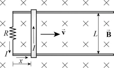
Figure
Write the expression for the induced emf in the metal rod.
Here,
Write the expression for the current in the metal rod.
Here,
Use equation (II) in (I) to solve for
Conclusion:
Substitute
Therefore, the current in the metal rod is
(b)
The energy dissipated in the resistor.
(b)
Answer to Problem 3P
The rate of energy dissipated in the resistor is
Explanation of Solution
Write the expression for the energy dissipated in the resistor.
Here,
Conclusion:
Substitute
Therefore, the energy dissipated in the resistor is
(c)
The magnetic force on the metal rod.
(c)
Answer to Problem 3P
The magnetic force on the metal rod is
Explanation of Solution
Write the expression for the magnetic force.
Here,
Conclusion:
Substitute
Therefore, the magnetic force on the metal rod is
Want to see more full solutions like this?
Chapter 20 Solutions
Physics


- A conducting single-turn circular loop with a total resistance of 5.00 is placed in a time-varying magnetic field that produces a magnetic flux through the loop given by B = a + bt2 ct3, where a = 4.00 Wb, b = 11.0 Wb/s2, and c = 6.00 Wb/s3. B is in webers, and t is in seconds. What is the maximum current induced in the loop during the time interval t = 0 to t = 3.50 s?arrow_forwardDesign a current loop that, when rotated in a uniform magnetic field of strength 0.10 T, will produce an emf =0 sin t. where 0=110V and 0=110V .arrow_forwardWhy is the following situation impossible? A conducting rectangular loop of mass M = 0.100 kg, resistance R = 1.00 , and dimensions w = 50.0 cm by = 90.0 cm is held with its lower edge just above a region with a uniform magnetic field of magnitude B = 1.00 T as shown in Figure P30.34. The loop is released from rest. Just as the top edge of the loop reaches the region containing the field, the loop moves with a speed 4.00 m/s. Figure P30.34arrow_forward
- A circular loop of wire of resistance R = 0.500 and radius r = 8.00 cm is in a uniform magnetic field directed out of the page as in Figure P31.54. If a clockwise current of I = 2.50 mA is induced in the loop, (a) is the magnetic field increasing or decreasing in time? (b) Find the rate at which the field is changing with time. Figure P31.54arrow_forwardA flat, square coil of 20 turns that has sides of length 15.0 cm is rotating in a magnetic field of strength 0.050 T. If tlie maximum emf produced in die coil is 30.0 mV, what is the angular velocity of the coil?arrow_forwardA rectangular conducting loop with dimensions w = 32.0 cm and h = 78.0 cm is placed a distance a = 5.00 cm from a long, straight wire carrying current I = 7.00 A in the downward direction (Fig. P32.75). a. What is the magnitude of the magnetic flux through the loop? b. If the current in the wire is increased linearly from 7.00 A to 15.0 A in 0.230 s, what is the magnitude of the induced emf in the loop? c. What is the direction of the current that is induced in the loop during this time interval?arrow_forward
- A square, flat loop of wire is pulled at constant velocity through a region of uniform magnetic field directed perpendicular to the plane of the loop as shown in Figure OQ23.9. Which of the following statements are correct? More than one statement may be correct. (a) Current is induced in the loop in the clockwise direction. (b) Current is induced in the loop in the counterclockwise direction. (c) No current is induced in the loop. (d) Charge separation occurs in the loop, with the top edge positive. (e) Charge separation occurs in the loop, with the top edge negative.arrow_forwardIn Figure P20.65 the rolling axle of length 1.50 m is pushed along horizontal rails at a constant speed v = 3.00 m/s. A resist or R = 0.400 is connected to the rails at points a and b, directly opposite each other. (The wheels make good electrical contact with the rails, so the axle, rails, and R form a closed-loop circuit. The only significant resistance in the circuit is R.) A uniform magnetic field B = 0.800 T is directed vertically downward. (a) Find the induced current I in the resistor. (b) What horizontal force F is required to keep the axle rolling at constant speed? (c) Which end of the resistor, a or b. is at the higher electric potential? (d) Alter the axle rolls past the resistor, does the current in R reverse direction? Explain your answer. Figure P20.65arrow_forwardA conducting rod of length = 35.0 cm is free to slide on two parallel conducting bars as shown in Figure P30.35. Two resistors R1 = 2.00 and R2 = 5.00 are connected across the ends of the bars to form a loop. A constant magnetic field B = 2.50 T is directed perpendicularly into the page. An external agent pulls the rod to the left with a constant speed of v = 8.00 m/s. Find (a) the currents in both resistors, (b) the total power delivered to the resistance of the circuit, and (c) the magnitude of the applied force that is needed to move the rod with this constant velocity. Figure P30.35arrow_forward
- Review. Figure P31.31 shows a bar of mass m = 0.200 kg that can slide without friction on a pair of rails separated by a distance = 1.20 m and located on an inclined plane that makes an angle = 25.0 with respect to the ground. The resistance of the resistor is R = 1.00 and a uniform magnetic field of magnitude B = 0.500 T is directed downward, perpendicular to the ground, over the entire region through which the bar moves. With what constant speed v does the bar slide along the rails?arrow_forwardThe bar in Figure OQ23.10 moves on rails to the right with a velocity v, and a uniform, constant magnetic field is directed out of the page. Which of the following statements are correct? More than one statement may be correct. (a) The induced current in the loop is zero. (b) The induced current in the loop is clockwise. (c) The induced current in the loop is counterclockwise. (d) An external force is required to keep the bar moving at constant speed. (e) No force is required to keep the bar moving at constant speed.arrow_forwardIn Figure P30.38, the rolling axle, 1.50 m long, is pushed along horizontal rails at a constant speed v = 3.00 m/s. A resistor R = 0.400 is connected to the rails at points a and b, directly opposite each other. The wheels make good electrical contact with the rails, so the axle, rails, and R form a closed-loop circuit. The only significant resistance in the circuit is R. A uniform magnetic field B = 0.080 0 T is vertically downward. (a) Find the induced current I in the resistor. (b) What horizontal force F is required to keep the axle rolling at constant speed? (c) Which end of the resistor, a or b, is at the higher electric potential? (d) What If? After the axle rolls past the resistor, does the current in R reverse direction? Explain your answer. Figure P30.38arrow_forward
 Physics for Scientists and Engineers with Modern ...PhysicsISBN:9781337553292Author:Raymond A. Serway, John W. JewettPublisher:Cengage Learning
 Principles of Physics: A Calculus-Based TextPhysicsISBN:9781133104261Author:Raymond A. Serway, John W. JewettPublisher:Cengage Learning
 Physics for Scientists and Engineers, Technology ...PhysicsISBN:9781305116399Author:Raymond A. Serway, John W. JewettPublisher:Cengage Learning
 Physics for Scientists and Engineers: Foundations...PhysicsISBN:9781133939146Author:Katz, Debora M.Publisher:Cengage Learning
 Physics for Scientists and EngineersPhysicsISBN:9781337553278Author:Raymond A. Serway, John W. JewettPublisher:Cengage Learning